Check how easy it is to get a Full Trunkey quote in minutes

Mixed Assembly Placement
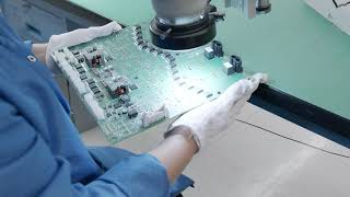
In mixed assembly placements, Printed Circuit Boards (PCBs) have both Surface Mount Devices (SMDs) and Pin-Through-Hole (PTH) components mounted on them. While placement of SMDs is directly on the solder pads on one or both sides, mounting PTH components is possible only through the top side of the PCB. Soldering SMDs on the top side of the PCB requires using the reflow method, while soldering components on the bottom side of the PCB requires using a wave soldering process.
As a circuit assembly using mixed components requires placing both SMDs and PTH components, special handling is necessary for the PCB for preparing it for the different soldering techniques.
Surface Mount Technology or SMT Soldering
It is possible to solder SMDs using reflow soldering technology as well as wave soldering technology, depending on their mounting on the top side or the bottom side of the PCB.
The reflow process requires using a stencil to apply solder paste on the pads of the PCB. The pick-and-place machine then places SMDs on the solder paste. The PCB with its components then passes through a preheating zone into the reflow zone. Here, the heat melts solder and anchors the leads of the SMDs to the PCB pads.
Wave Soldering Technology
Once the reflow process has finished soldering SMD components on the top side of the PCB, the operator must turn the board over for placing additional SMD components on its underside. A glue dispenser then places dots of glue at the center of the components’ position. The pick-and-place machine then places SMDs on the glue dots. The board goes into an oven for curing the glue.
After the glue cures, the operator turns the board over again, and passes it through a wave soldering machine. Here a jet of molten solder solders the glued SMD components from below.
When it is necessary to add PTH components, some additional steps are required. After reflowing the SMDs on the top side and gluing the SMD components to the underside, the operator must insert the leads of the PTH components into their respective holes from the top side of the board. The operator then passes the board through the wave soldering machine for soldering the PTH components and SMDs glued on the underside of the board.
Mixed Component Assembly Issues
When mixed component assembly is necessary on a PCB, designers must take care of some special considerations:
- When inserting PTH components using insertion machines, the components must have adequate spacing to allow the head to maneuver.
- When using lead-free solder, the operator must set the thermal profile for the specific type of solder.
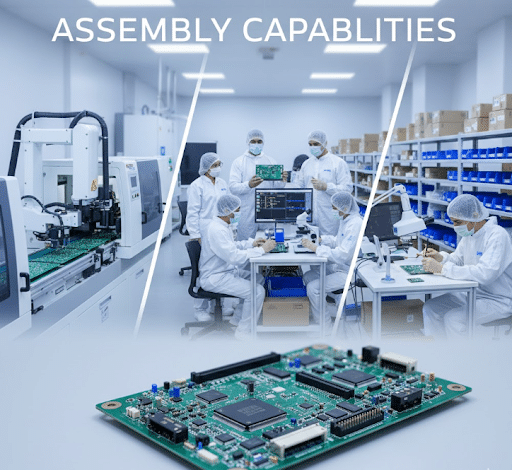
PCB Trace Technologies Inc has enough expertise and experience in all types of assembly—SMD, PTH, and mixed component assembly.
Our engineers at PCB Trace Technologies Inc will work with you on both the engineering as well as the design for your mixed component assembly PCB.
For more information on mixed component assembly, call us today at 1 408-580-0722, or contact us at [email protected].


Increased Production Panel Output
We can now ship 100 production panels of 18"x24" in 5-7 working days for 2 to 10 layer designs.
A glimpse into PCB Trace